Contact Information

Theodore Lowe, Ap #867-859
Sit Rd, Azusa New York

We Are Available 24/ 7. Call Now.

But why?

I was having stability issues with WiFi, and the Yeelight intergration of Home Assistant. After searching Google for information on how to flash this kind of led strip I found no results. So I tried it myself. And success! In this post I’m going to show you exactly how I did it.

What do you need?

  • The Yeelight LED strip model YLDD05Y (duhh)
  • Homeassistant running with ESPHome
  • USB FTDI programmer
  • Soldering iron
  • Wires

Crack it open!

The led strip has no screws or anything. The best way to open it is to pry a screwdriver in between the two layers of plastic. It will open easily. 

Yeelight LED strip with USB debugger attached

Solder to testpoints

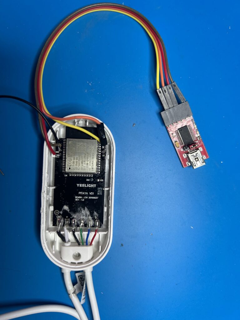
We want to re-program the ESP on the PCB. Yeelight left us some test points on the PCB we can use 🙂 Solder some wires to the following points, and connect them to the FTDI:

PCB -> FTDI

  • TX -> RX
  • RX -> TX
  • VCC -> +3.3v
  • GND-> GND

Prepaire ESPHome and flash

Make sure you are running the latest version of ESPHome in your Homeassistant. The ESPHome version I used was v2021.10.3 Create a new device, and add it to ESPHome. You can skip all the upload steps for now. We need to make some changes to the config first.
 
Credits the repo:  https://github.com/syssi/esphome-yeelight-ceiling-light for giving me some examples of other Yeelight devices.
 
Change your ESPHome configuration to the example below. Make sure you replace the placeholders to match you configuration.
substitutions:
  name: yeelight-s1
    
esphome:
  name: ${name}

esp32:
  board: esp32doit-devkit-v1
  framework:
    type: esp-idf
    sdkconfig_options:
      CONFIG_FREERTOS_UNICORE: y
    advanced:
      ignore_efuse_mac_crc: true

# Enable logging
logger:

# Enable Home Assistant API
api:

ota:
  password: ""

wifi:
  ssid: ""
  password: ""

  # Enable fallback hotspot (captive portal) in case wifi connection fails
  ap:
    ssid: "Yeelighjt-S1"
    password: "QVZf6CAx3rwf"

output:
  - platform: ledc
    pin: GPIO13
    id: output_red
  - platform: ledc
    pin: GPIO14
    id: output_green
  - platform: ledc
    pin: GPIO5
    id: output_blue

light:
  - platform: rgb
    name: "${name} rgb light"
    red: output_red
    green: output_green
    blue: output_blue
    gamma_correct: 0

To flash the ESP on the board you need to connect test point IO0 to GND when powering on. This will start the ESP in flash mode. Now you can use ESPHome to flash the firmware. I used the option “Plug into this computer”. Select the FTDI, and start flashing! The software can take a while to compile and upload. So be patient.

After you have successfully flashed the ESP, disconnect power and reconnect power to reboot. Verify in ESPHome that the new device is online. Now desolder the test points and test the led strip by connecting the original power supply.  

Share:

administrator

2 Comments

  • Henry, August 23, 2023 @ 8:27 am Reply

    Hi Wouter,
    dank u wel for the tutorial. Yesterday, I flashed my light strip that was literally burried in a closet for over two years. The flashing process was easy, but unfortunately the case cover was glued, so there was no chance to open it without destroying the case. Hope I can find a 3D print file to replace it…

    I also realised that the button no longer works. Is this expected?

    Best,
    H.

  • Leon, February 26, 2024 @ 2:21 pm Reply

    output:
    – platform: ledc
    pin: GPIO13
    id: output_red
    – platform: ledc
    pin: GPIO14
    id: output_green
    – platform: ledc
    pin: GPIO5
    id: output_blue

    light:
    – platform: rgb
    id : main_led
    name: “${name} rgb light”
    red: output_red
    green: output_green
    blue: output_blue
    gamma_correct: 0

    – platform: status_led
    id: stat_blue_led
    name: “Switch blue led state”
    pin:
    number: GPIO4
    inverted: yes
    – platform: status_led
    id: stast_orange_led
    name: “Switch orange led state”
    pin:
    number: GPIO16
    inverted: yes

    binary_sensor:
    – platform: gpio
    pin:
    number: GPIO19
    inverted: yes
    name: “Button”
    on_press:
    then:
    – light.toggle: main_led

Leave a Reply

Your email address will not be published. Required fields are marked *